Aircraft Fuel System Schematic
Fuel system aircraft diagram typical systems tank tanks air line may Aircraft systems: aircraft turbine engine fuel system requirements Fuel aircraft block diagram system figure eng iut 45c adv ts
Aerospace and Engineering: Airliner fuel system
Figure 2.1. fuel system schematic diagram. Fuel engine system aircraft injection continental systems multi airplane teledyne aviation study typical performance single figure using high Fuel 737 b737 engine schematic diagram air jet aviation system lines ng
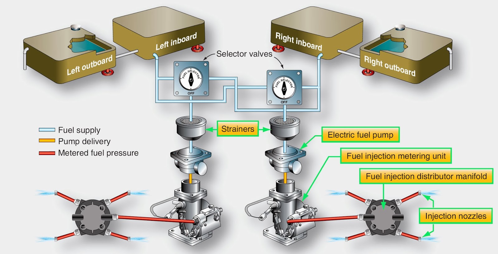
Fuel aircraft system injection wing high engine systems reciprocating twin light simple distribution manifold its figure
Free aviation study: small multi-engine aircraft fuel systemsLight aircraft fuel system design Fuel system aircraft dc systems distribution transfer engine cockpit jet controls complex feed components aerospace storage refuel helicopter dump deliveryAircraft fuel system modeling.
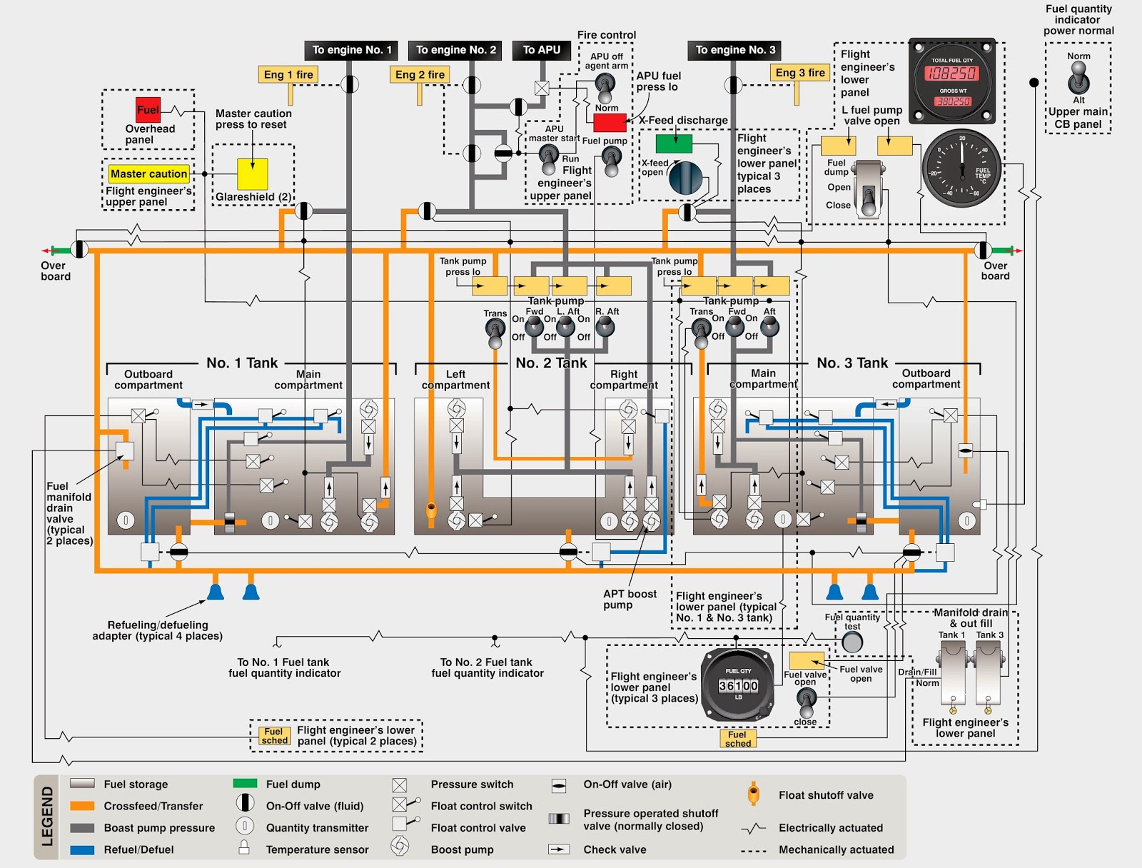
Fuel system diagram aircraft schematic aviation dc reciprocating systems study figure mainAircraft systems: aircraft fuel systems Free aviation study: large reciprocating aircraft fuel systemsFigure 7: aircraft fuel system block diagram.

Fuel system aircraft schematic typical modeling simulation engine single
Fuel aircraft engine reciprocating tanks single systems tank valve vent pumps small uses figure selector offSchematic fuel diagram system figure chapter systems accessories aircraft 172 cessna selector wiring failureLeft? right? or both?.
Aircraft fuel systemsFuel aircraft system diagram systems generic gif interactive Fixed wing and rotary wing aircraft fuel systemsSimulink layer.

Fuel engine system turbine aircraft schematic control requirements systems
737 aircraft operation fuelingSchematic of the aircraft fuel system. Terdampar dipinggirkan: aircraft fuel systems(pdf) modeling and simulation of a single engine aircraft fuel system.
Aerospace and engineering: airliner fuel system737 fuel system schematic diagram .

Light Aircraft Fuel System Design

Aircraft Fuel Systems
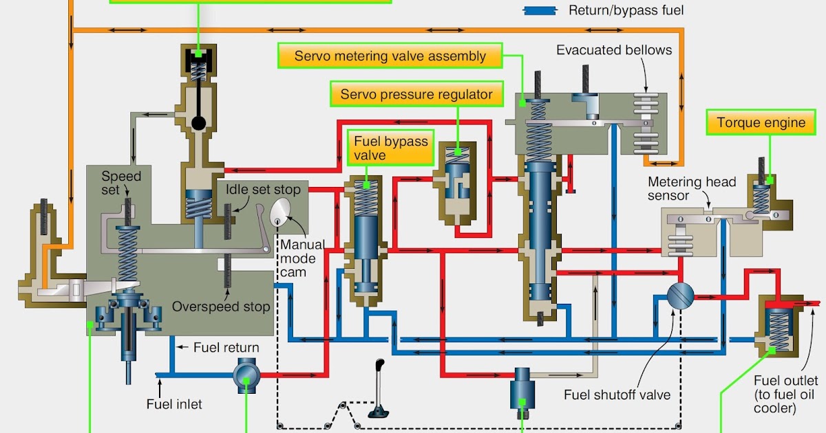
Aircraft Systems: Aircraft Turbine Engine Fuel System Requirements

Left? Right? or Both? - Cessna 172 Fuel Selector and Engine Failure - RPX

Figure 2.1. Fuel System Schematic Diagram.
Aerospace and Engineering: Airliner fuel system

Aircraft systems: Aircraft Fuel Systems

terdampar dipinggirkan: aircraft fuel systems

Schematic of the aircraft fuel system. | Download Scientific Diagram