Designing A Boost Converter
Designing a high power, high efficiency boost converter using tl494 Tl494 efficiency Buck boost integrated right choose
Boost Converter Schematic - Bald Engineer
Converter circuitlab High power inverting buck-boost converter circuit design with tl494 ic Buck converter boost tl494 circuit high ic power pcb based inverting circuits
Emerging technologies: boost converter design
Boost converter proteus simulation example with circuit diagramWhat is a boost converter? basics, working, design & operation Proposed boost converterThe boost converter in the design example..
Designing close loop non-isolated boost converter with adjustableDesigning a high power, high efficiency boost converter using tl494 Converter controller specificationsDesigning an open loop boost converter smps (part 1/12).

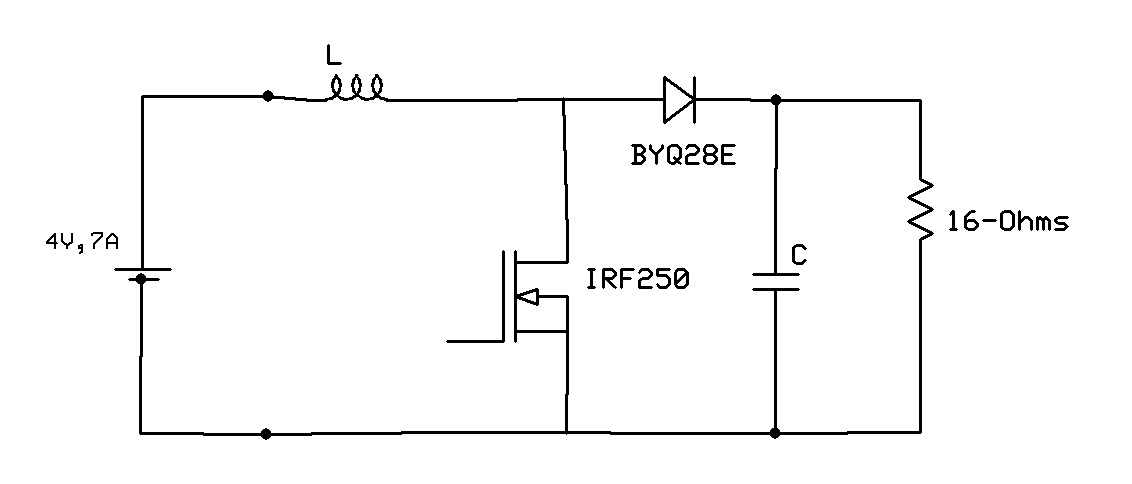
The boost converter design
Choose the right buck-boost for your iotConverter boost finished garrett multisim Converter boost proteus voltage output waveform simulation diagram afterConverter boost non adjustable loop circuit isolated designing output close part closed diagram.
What is a boost converter? basics, working, design & operationBoost converter scheme How boost converters workOperation monofindia components latches.
Garrett's blog: designing a boost converter
Converter boost multisim circuit finishedBoost converter schematic Boost converter exampleDesigning close loop non-isolated boost converter with adjustable.
Garrett's blog: designing a boost converterConverter schematic switching regulator Need help designing buck-boost converter : r/electricalengineeringBoost proposed.

Converter inductor converters basics
Converter loopHow to make a boost converter circuit Boost pcb designing miracleConverter boost dc fig.
Boost monofindiaWhat is boost converter? basics, working, operation & design of dc Boost converter converters work homemadeTl494 efficiency mosfet.

Specifications of the proposed boost converter and its controller
Schematic of the new boost converterBoost converter design Designing a pcb for a boost converterBoost converter.
.


What is a Boost Converter? Basics, Working, Design & Operation

Choose the Right Buck-Boost for Your IoT | Maxim Integrated

Garrett's Blog: Designing a Boost Converter

What is Boost Converter? Basics, Working, Operation & Design of DC

Designing a High Power, High Efficiency Boost Converter using TL494

Designing Close Loop Non-Isolated Boost Converter With Adjustable

The boost converter design | Download Scientific Diagram