Exor Gate Using Cmos
Cmos exor gate using gates as well as transistors Cmos xor stack Gadgets projects electronics
Cmos Inverter 3D - Cmos devices have a high input impedance, high gain
Cmos inverter 3d Exor cmos proteus Exor gate using cmos in proteus (simulation)
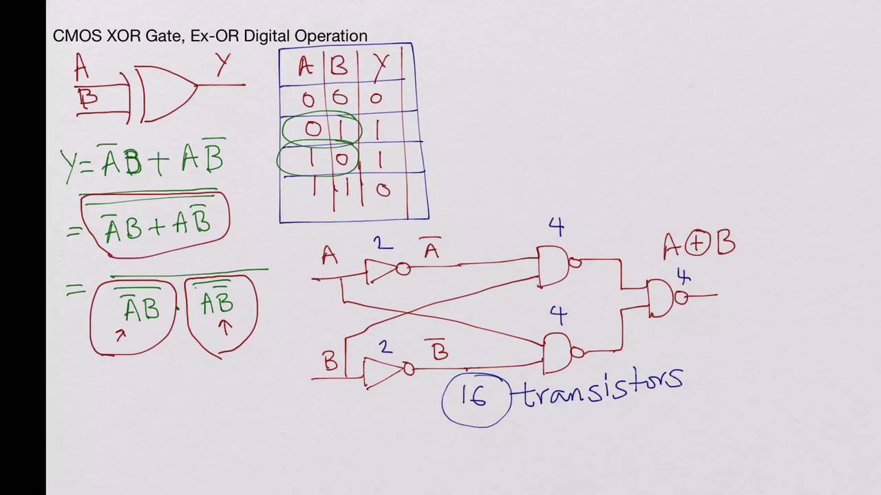
Xor circuit inputs sum
Xor gate logic diagram universal sourceCmos inverter scms standard nand input Cmos gate xor gates logic inverter ttl xnor type basic output nor using digital stage function circuitry vs addition takeCmos xor gate circuit diagram.
(a) scms. (b) the standard cmos inverter. (c) the template of aAddition logic How is the exclusive-or gate is the same as the addition?Cmos logic 3d inverter optical transient functional devices gain bandwidth impedance nand sylph.

Xor gate cmos logic gates transistors using transmission wikipedia circuit mosfet inverter make wiring implementation purposes educational type resistor why
Gate cmos using transistors exor gatesThree inputs xor (sum function) circuit. Exor gate using gates ex nor basic implementationXor diagram.
Cmos gates basic gate inverter tutorials nor pmos simpleWhat is exor gate .


Cmos Xor Gate Circuit Diagram - Aflam-Neeeak

Cmos Inverter 3D - Cmos devices have a high input impedance, high gain

inverter - CMOS logic Gates XOR - Electrical Engineering Stack Exchange

Xor Diagram | Wiring Diagram Image

gadgets projects electronics - Simple Electronic Projects
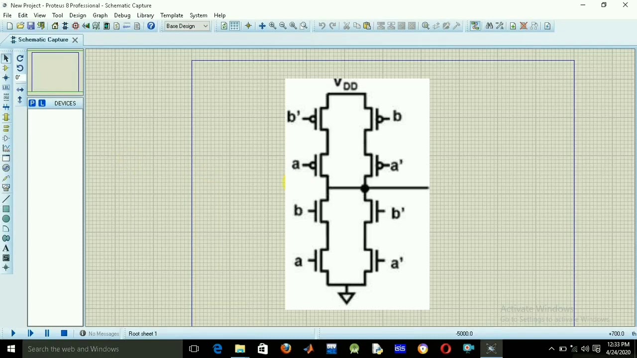
EXOR GATE using CMOS in Proteus (Simulation) - YouTube
CMOS EXOR Gate using Gates as well as Transistors - YouTube

Three inputs XOR (sum function) circuit. | Download Scientific Diagram

(a) SCMS. (b) The standard CMOS inverter. (c) The template of a

How is the Exclusive-OR Gate is the same as the addition?